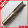
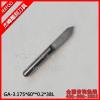
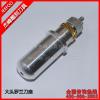
cnc blade bits for making
Engraving Tools-Guangzhou Jeefoo Cnc Tools / 2011-10-19
Refers to the flat two-dimensional cavity closed contour as the boundary of the flat-bottomed pit straight wall. The general two-dimensional cavity machining process is: stay out of the boundary along the contour precision machining allowance, first with the flat bottom of the cutter or line with a ring cutting method cutting tool path, milling excess material to the cavity, and finally along the cavity bottom and tool path contour, precision milling and boundary shape of the cavity bottom. When the cavity deeper, will have to be rough layer, then also need to define the depth of each layer of rough and the actual depth of the cavity to calculate how many layers need to be rough points.
1.1, line Qiefa Jia working tool path generation
This processing method is relatively simple calculation of the tool path, the basic process is: first determine the angle of feed path (with the X-axis angle), then the tool radius and processing requirements to determine tool path step, then the cavity under the plane boundary contour (including the island shape), the tool radius and cutting precision machining allowance calculated tool path line, and finally ordered the line segment connecting the tool path, the way to a one-way connection can also be a two-way, according to process requirements. One-way connection for tool changing needs of carrying knives, face when they need carrying knives island. For the calculation of tool path segments connecting the islands, you need to calculate the following steps:
(1) plane cavity boundary (including the island's boundary) contours of the series and ordered: the body into a closed boundary contour.
(2) border (including the island's borders) outline the formation of the equidistance line: contour of the equidistance line distance from the border and the tool allowance for the fine and the radius.
(3) line work lines therefore legitimate tool path calculation:
(4) the orderly series of tool path segments;
(5) cavity and islands along the equidistance line movement, the last tool path generation.
1.2, Central Qiefa Jia working tool path generation
Work is generally along the ring cavity Qiefa Jia go equidistant boundary line, tool path calculation is relatively complex, and its advantage is that the cutting cutter way of the same (or reverse cis milling milling). Within the grounds of Central Qiefa Jia work points to cut the outer ring and inner ring cut from the outside.
Qiefa Jia cavity ring plane tool path calculation work in a certain sense, can be summarized as plane closed contour calculation of the equidistance line. A current common equidistance line method is a direct offset method, the algorithm steps are as follows:
(1) offset by a certain distance of each closed contour curves of a boundary equidistant lines were calculated;
(2) of equidistant lines of each crop or extension necessary, connect to form a closed curve.
(3) handling the line equidistant from the intersection, and the validity of test to determine when and islands, the boundary contour interference, remove redundant ring, the offset distance be closed based on the equidistance line.
(4) Repeat the process until complete traversal of all regions to be processed.
This algorithm can handle any curve of a closed boundary contour, the deficiencies must be offset curve of each section of the junction of the processing complex, generated in the process to remove excess bias ring, a lot of validity of the test in order to avoid interference, efficiency of the algorithm notices, and in some cases redundant ring is very difficult to determine treatment.
Shaver, Central more advanced modern engineering tool path is calculated as the processing region to be divided into several sub-regions, each sub-region can be rough with large knives, and finally finishing with a small tool for shaping. Voronoi diagram is an effective sub-regional division ring therefore legitimate method of work, the core idea is that each sub-region all the pitch contour of a closed section (linear or circular) contour edge recently, when the sub-regional division after structure in each sub-region corresponding to the edge of the equidistance line profile can be made to ensure convergence of the equidistance line between the right and avoid the different intersection between the equidistance line, interference checking and cutting processing.
1.3, based on the Voronoi diagram Shaver Pocket Tool Path Generation Engineering
(1) Voronoi diagram
Each polygon form a straight line segment or arc is called the boundary element, the element e of the Voronoi region is the e smaller than the distance to other elements of the set of points, two elements common edge Voronoi region is called Voronoi edges, it is above point to the same distance from the two boundary elements, it is also known bisector, bisector of the two boundary elements as the definition of elements. Face convex, respectively, for two adjacent edges of the vertical line as a Voronoi edge. Voronoi edge is expressed as a parameter to point to the Voronoi edge of the boundary element distance as a parameter. Two endpoints of Voronoi edges, the smaller distance to the border point, which is the parameter region corresponding to the Voronoi edge point of the lower bound, called the Voronoi edge of the tail; to the border from the larger point, that is, parameters corresponding to the Voronoi edge points on the boundary region, called the Voronoi edge of the head.
The intersection is called Voronoi Voronoi edge node. A Voronoi node is connected to at least two Voronoi edges. If a Voronoi Voronoi edge node is a head, called the Voronoi edge into the node for the Voronoi edge; the other hand, the Voronoi edge is the edge of a Voronoi edge.
Voronoi diagram is a plane polygon within the polygon boundary area is divided into various elements of Voronoi region.
(2) Based on Voronoi Diagram Pocket therefore legitimate work tool path generation
When a cavity area Voronoi diagram generation, you can proceed to generate tool path, the method is: a boundary element from the Voronoi area, beginning with the given offset distance d of the boundary element calculation of the equidistance line, the equidistance Voronoi area line and the intersection of two Voronoi edges, corresponding to the intersection of two Voronoi edge of the parameters are d, the equidistance line between the two is the intersection of a tool path. Traverse the boundaries of all elements of the cavity, and all the parameters d Voronoi edge equidistant lines in the intersection linking the border when the traversal back to the starting element, namely the formation of a closed tool path. Then reduce the offset distance d, repeat the process, can generate the tool path Yi closed


 Free Hotline:400-666-3853 粤ICP备12044779号-4